by
Robert Q. Riley
with tilting three-wheeler contributions by
Tony Foale
Revised September 2014
The idea of smaller, energy-efficient
vehicles for personal transportation seems to naturally introduce the three wheel
platform. Opinions normally run either strongly against or strongly in favor of the
three wheel layout. Advocates point to a mechanically simplified chassis, lower
manufacturing costs, and superior handling characteristics. Opponents decry the
three-wheeler's propensity to overturn. Both opinions have merit.
Three-wheelers are lighter and less costly to manufacture. But when poorly designed
or in the wrong application, a three wheel platform is the less forgiving layout.
When correctly designed, however, a three wheel car can light new fires of enthusiasm
under tired and routine driving experiences. And today's tilting three-wheelers,
vehicles that lean into turns like motorcycles, point the way to a new category of
personal transportation products of much lower mass, far greater fuel economy, and
superior cornering power.
Inherently Responsive Design
Designing to the three-wheeler's inherent characteristics can produce a
high-performance machine that will out corner many four-wheelers. A well designed
three-wheeler is likely to be one of the most responsive machines one will ever experience
over a winding road. Superior responsiveness is primarily due to the three-wheeler's rapid
yaw response time.
Yaw response time is the time it takes for a vehicle to reach steady-state cornering
after a quick steering input. A softly sprung four-wheeler will have a yaw response time
of about 0.30 seconds, and a four wheel sports car will respond in about half that time. A
well designed three-wheeler can reach steady-state cornering in as little as 0.10 seconds,
or about 33 percent quicker than a high-performance four wheel car.
Quick steering response has nothing to do with the number of wheels or how they are
configured. It is a byproduct of reduced mass and low polar moment of inertia. A typical
three-wheeler is lighter and has approximately 30 percent less polar moment than a
comparable four wheel design. Here's a link to video and driving report on the new Morgan three-wheeler, which is a close copy of the one built in the twenties and thirties. Notice that the vehicle's side-by-side wheels are located wide and the overall height is low. Location of the center of gravity is crucial to a three-wheeler's handling and rollover stability.
Rollover Stability of Conventional Non-Tilting Three-Wheeler
A conventional, non-tilting three wheel car can equal the rollover resistance of a four
wheel car, provided the location of the center-of-gravity (cg) is low and near the
side-by-side wheels. Like a four wheel vehicle, a three-wheeler's margin of safety against
rollover is determined by its L/H ratio, or the half-tread (L) in relation to the cg
height (H). Unlike a four-wheeler, however, a three-wheeler's half-tread is determined by
the relationship between the actual tread (distance between the side-by-side wheels) and
the longitudinal location of the cg, which translates into an "effective"
half-tread. The effective half-tread can be increased by placing the side-by-side wheels
farther apart, by locating the cg closer to the side-by-side wheels, and to a lesser
degree by increasing the wheelbase. Rollover resistance increases when the effective
half-tread is increased and when the cg lowered, both of which increase the L/H ratio.
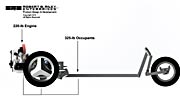
A simple way to model a three-wheeler's margin of safety against rollover is to
construct a base cone using the cg height, its location along the wheelbase, and the
effective half-tread of the vehicle. Maximum lateral g-loads are determined by the tire's
friction coefficient. Projecting the maximum turn-force resultant toward the ground forms
the base of the cone. A one-g load acting across the vehicle's cg, for example, would
result in a 45 degree projection toward the ground plane. If the base of the cone falls
outside the effective half-tread, the vehicle will overturn before it skids. If it falls
inside the effective half-tread, the vehicle will skid before it overturns. To see a
drawing showing a base-cone illustration of single front wheel (1F2R) and single rear
wheel (2F1R) vehicles, click on: Single Front & Single
Rear Wheel Comparison (23k).
The foregoing is a simple rigid-body analysis and it does not consider the effects of suspension, rebound, and body-roll inertial forces. It therefore provides an approximation of rollover threshold under dynamic conditions.
Oversteer/Understeer Characteristics
The single front wheel layout naturally oversteers and the single rear wheel layout
naturally understeers. Because some degree of understeer is preferred in consumer
vehicles, the single rear wheel layout has the advantage with the lay driver. Another
consideration is the effect of braking and accelerating turns. A braking turn tends to
destabilize a single front wheel vehicle, whereas an accelerating turn tends to
destabilize a single rear wheel vehicle. Because braking forces can reach greater
magnitudes than acceleration forces (maximum braking force is determined by the adhesion
limit of all three wheels, rather than two or one wheel in the case of acceleration), the
single rear wheel design has the advantage on this count. Consequently, the single
rear wheel layout is usually considered the preferred platform for a high-performance
consumer vehicle in the hands of the non-professional driver. But racecar drivers often prefer slight oversteer to understeer. Oversteer gives the skilled driver the ability to perform extreme maneuvers that an understeering vehicle would simply mush through and refuse to perform. Moreover, by varying tire size and pressure, a single front wheel vehicle can be designed for neutral steer with oversteer present only at the limit of adhesion. Much depends on the details of the design, as well as driver preferences and skills.
Existing Designs
The following will give the reader a better understanding of the center of gravity factors that determine the rollover stability of a three wheel platform. Obviously, this writer considers rollover stability perhaps the most important factor in the design of the three-wheel vehicle, but there are many other considerations as well. And within limits, a vehicle that lacks high rollover stability can be a safe one. A panel truck, for example, has a rollover threshold of only about 0.65-g lateral force. But one does not see the roadsides littered with overturned panel trucks. In general, drivers sense the limits of their vehicles and drive accordingly.
Trihawk
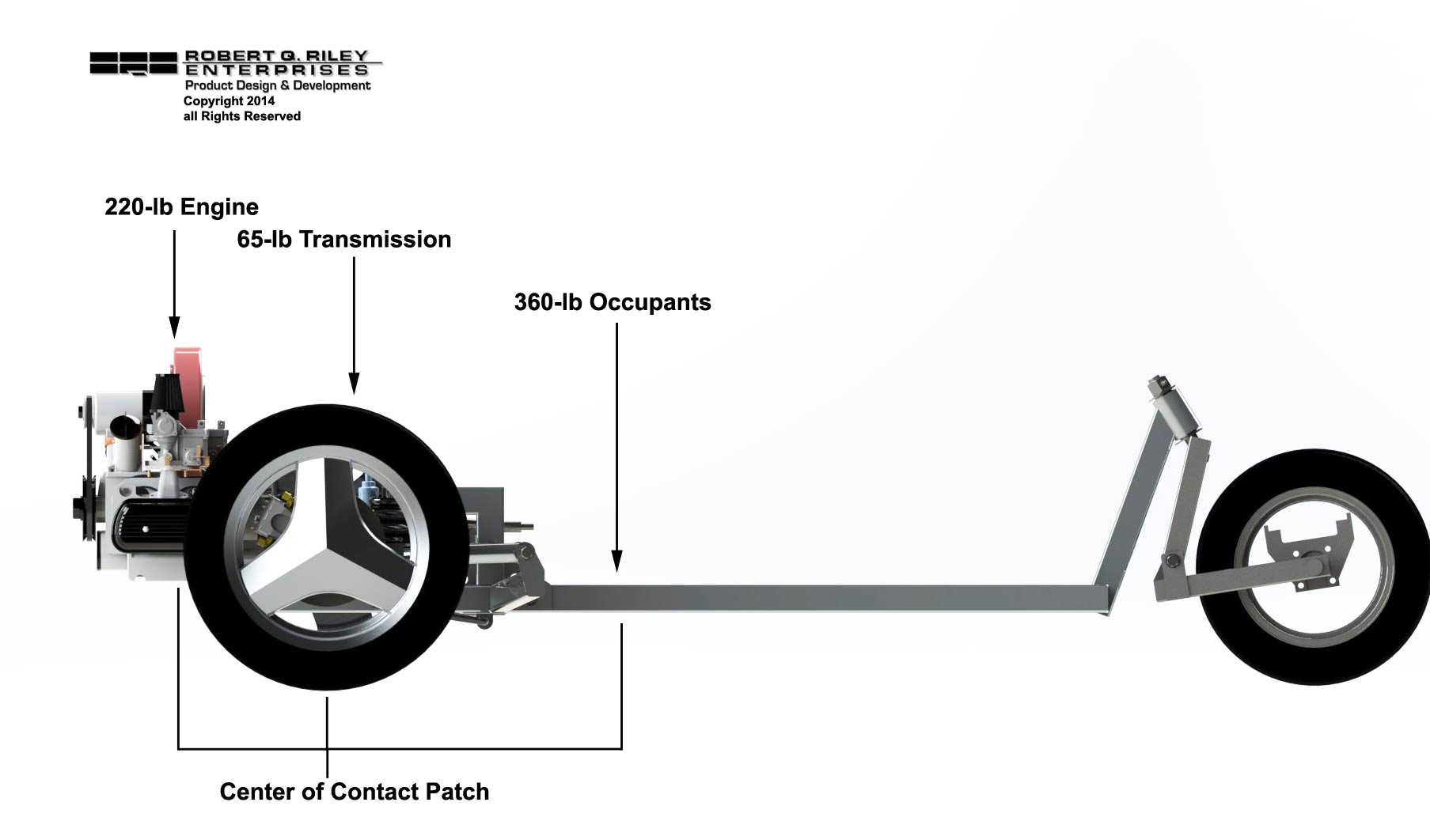
Trihawk is a good example of a well-designed three-wheeler, in terms of dynamic stabiltiy. It's a 2F1R design with power delivered to the two front side-by-side wheels. This means that more power can be delivered to the ground via the two powered front wheels. One typical problem with this layout, however, is that humans are built with legs that extend forward in a seated position. The feet therefore establish the forward limits of the occupants (the feet cannot extend through the drive axles), which forces the center of mass rearward toward the single rear wheel. This is exactly the opposite of the designer's need to locate the vehicle's center of gravity near the side-by-side wheels and away from the single-wheel end of the vehicle. Two occupants result in roughly 300 or more pounds located quite far from the front axle. Trihawk engineers solved much of this problem by locating the Citroen engine ahead of the front axle where it tends to offset the mass of the occupants. Additionally, Trihawk has a very low seating position and a wide track. As a result, the vehicle is among the best-handling three-wheelers around.
Here's a link to a review by Road & Track magazine.
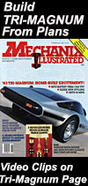
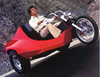
Motorcycle-Based Three-Wheelers
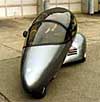
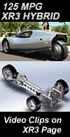
A number of 2F1R vehicles have used a motorcyle-plug-in as the basis of the design. T-Rex is a modern production vehicle built on this layout. Like our Tri-Magnum and Ron Will's Phantom, T-Rex uses an entire motorcycle, sans the front fork and wheel, to power the vehicle. The beauty of this approach is that it takes advantage of a well proven production motorcycle power train, already packaged in a frame. The down side is that large motorcycles are heavy and costly. But fortunately, much of a motorcycle's mass is well forward in the frame. And by locating the motorcycle as far forward as possible, and placing the occupants well forward and between the side-by-side wheels, it's possible to produce a vehicle that has excellent rollover stability. A wide and low design completes the formula. Our XR3, although not based on a motorcycle, has a front track that is wider than that of a Mustang, and it is a very low vehicle too.
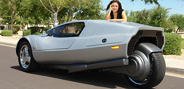
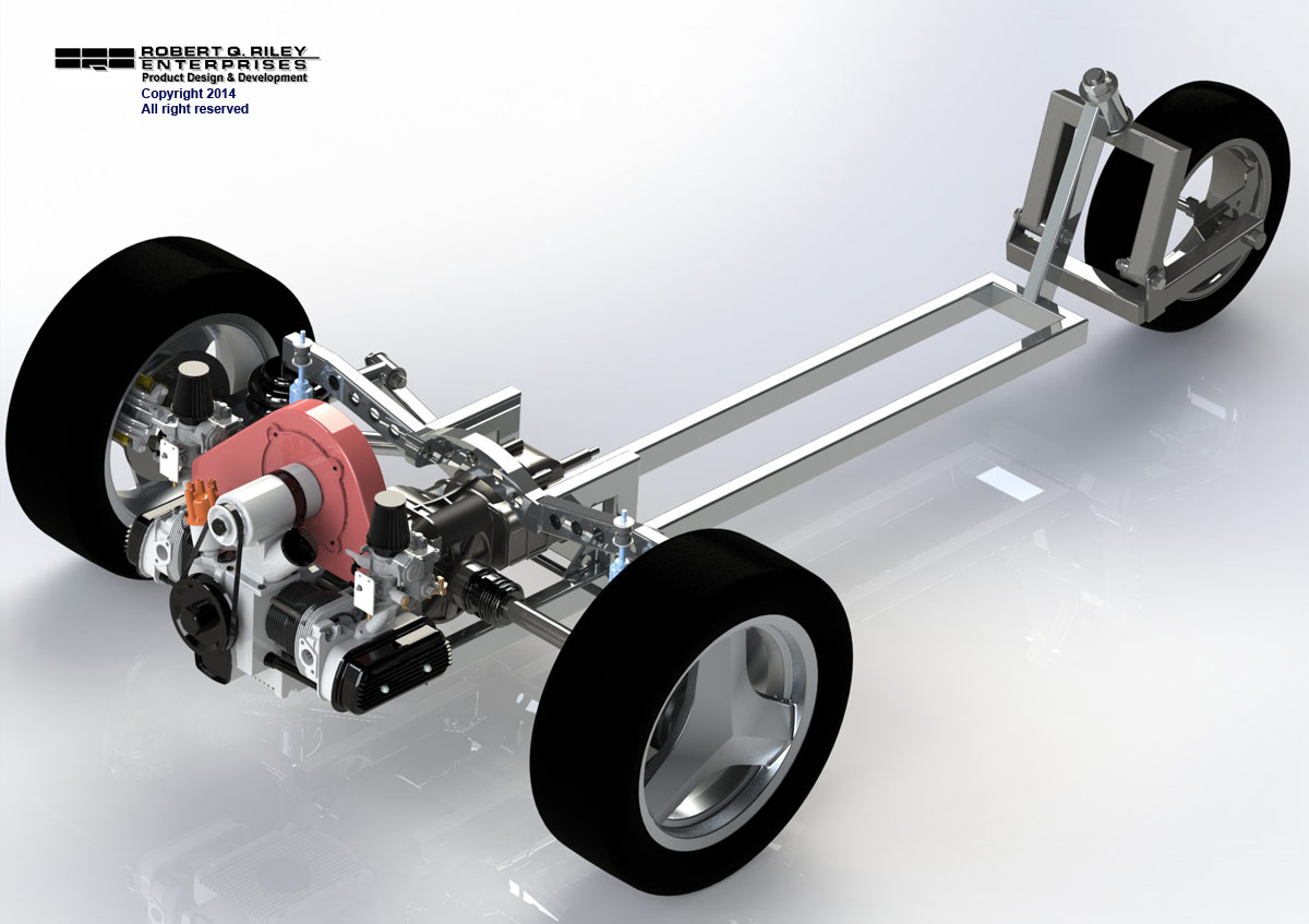
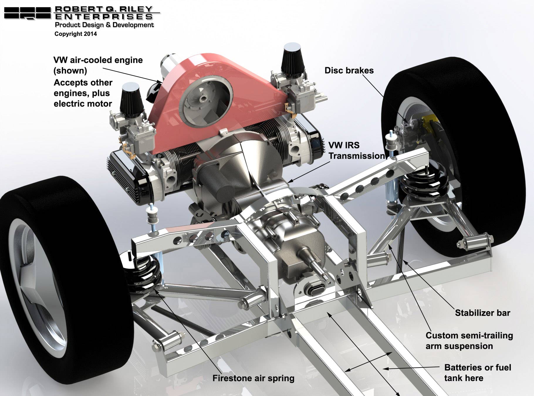
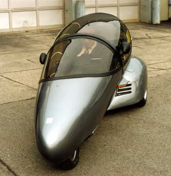
Trimuter
Our own Trimuter is among the most dynamically stable 1F2R designs around. The advantage of this layout is that the seated human body is ideally shaped with legs extending forward and the primary mass rearward where it can be easily placed near the side-by-side wheels. In this writer's experience, control of the vehicle's center of gravity is easier with a 1F2R than it is with a 2F1R layout. This layout also lends itself to a streamlined body. The downside is that braking in a turn projects the vector of forces toward the front where it tends to reduce rollover stability. This can be offset by locating more of the mass rearward - locating the center of gravity more torward the rear axle. This also has the effect of resulting in an over-steering vehicle. This can be largely offset by using larger rear wheels/tires and a smaller front wheel/tire, which again helps aerodynamics. But what's known as "limit oversteer" still remains. In other words, at the limit of adhesion a 1F2R layout will spin out. But many understeering vehicles will also spin out at the limit of adhesion, especially when power is delivered to the rear wheel(s).
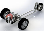
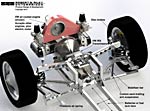
Click on the images below for a new chassis design (under deveopment at this writing) that will enhance Trimuter's dynamic stability and give it much greater performance and higher speeds. Notice that much of the mass naturally ends up near the rear axle where it provides good rollover stability. As a theoretical extreme, if all the mass were located near the rear axle, the designer could forget about "effective half-tread" (foregoing discussion) because the vehicle would have the rollover stability of a four-wheel vehicle. Of course that's not mechancially possible, or even desirable. The front wheel has to be correctly loaded too. In this layout, however, even a small amount of mass up front (a starting battery, for example) can fine-tune the longitudinal CG location for the best all around handling characteristics.
Tilting Three-Wheelers (TTWs)
 Tilting three-wheelers, vehicles that lean into turns like motorcycles, offer increased
resistance to rollover and much greater cornering power - often exceeding that of a four
wheel vehicle. And designers are no longer limited to a wide, low layout in
order to obtain high rollover stability. Allowing the vehicle to lean into
turns provides a much greater latitude in the selection of a cg location and the
separation between opposing wheels. Tilting three-wheelers, vehicles that lean into turns like motorcycles, offer increased
resistance to rollover and much greater cornering power - often exceeding that of a four
wheel vehicle. And designers are no longer limited to a wide, low layout in
order to obtain high rollover stability. Allowing the vehicle to lean into
turns provides a much greater latitude in the selection of a cg location and the
separation between opposing wheels.
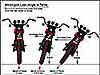
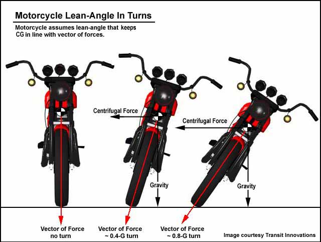
Consider that a motorcycle has no side-by-side wheels, yet it does not
overturn when going around corners. A motorcycle negotiates turns by assuming a lean
angle that balances the vector of forces resulting from the turn rate. The rider
leans the motorcycle into the turn so it remains in balance with the forces that are
acting on it. As long as the motorcycle's lean angle matches the vector of forces in
a turn (resultant), it will not overturn. In order to stay in balance with turn
forces under all possible conditions, however, a motorcycle must be able to lean at an
angle of 50-55 degrees before any part of the machine contacts the ground.
Three and four wheel vehicles can also be made to lean into turns.
But with tilting vehicles equipped with side-by-side wheels, other physical and geometric
realities come into play. For example, a vehicle having a wide body may contact the
ground even at moderate lean angles, which will make it impossible to stay in balance with
turn forces at the upper extremes. In addition, the greater the separation between
the side-by-side wheels, the greater the wheel movement at equivalent lean angles.
The movement of the side-by-side wheels can become excessive even at relatively small
angles of lean in vehicles having a track approaching that of conventional automobiles.
And the mechanical challenges of accommodating steering, bounce, and tilting, along
with the angular limitations of CV joints on powered axles, places additional limitations
on the lean angle of tilting multi-track vehicles. As a result, much of the
recent work on tilting suspension systems has concentrated the three wheel platform.
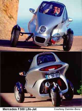
The Project 32 Slalom (1F2R) and the Mercedes F300 Life-Jet (2F1R) are excellent examples of
modern tilting three wheel designs.
Free-Leaning versus Active Lean Control
Tilting three-wheelers can be free-leaning and controlled by the rider,
just like ordinary motorcycles. However, if the mechanical limit of lean is less
than is necessary to balance turn forces under all possible conditions, then some form of
active (forced) lean control must be used to account for turns that exceed the lean limit.
This is usually accomplished by hydraulic or electro-mechanical actuators operating
on signals from an electronic control unit (ECU). Normally, the ECU processes
signals from sensors that monitor lateral acceleration, vehicle yaw and lean angle,
steering angle, and other relevant factors, then provides control output to the lean
actuators. Another advantage of active lean control is that the operator is no
longer required to balance the vehicle, as when operating a motorcycle. With active
lean control, the vehicle is driven just like an ordinary automobile, and the lean control
system takes care of the rest.
Rollover Threshold of TTWs
The rollover threshold of a TTW is determined by the same dynamic forces
and geometric relationships that determine the rollover threshold of conventional
vehicles, except that the effects of leaning become a part of the equation. As long
as the lean angle matches the vector of forces in a turn, then, just like a
motorcycle, the vehicle has no meaningful rollover threshold. In other words, there
will be no outboard projection of the resultant in turns, as is the case with non-tilting
vehicles. In a steadily increasing turn, the vehicle will lean at greater and
greater angles, as needed to remain in balance with turn forces. Consequently, the
width of the track is largely irrelevant to rollover stability under free-leaning
conditions. With vehicles having a lean limit, however, the resultant will begin to
migrate outboard when the turn rate increases above the rate that can be balanced by the
maximum lean angle. Above lean limit, loads are transferred to the outboard wheel,
as in a conventional vehicle.
 Tony Foale, author of Motorcycle Chassis Design,
explains the behavior of an all-leaning-wheels TTW in terms of a virtual motorcycle wheel
located between the two opposing real wheels. In a balanced turn, the resultant
remains in line with the virtual motorcycle wheel. But in turns taken above the
limit of lean, the resultant projects to the outside of the virtual wheel (vehicle
centerline), according to the magnitude of turn forces in excess of those at lean
limit. It's also important to note that the vehicle cg moves inboard as the vehicle
leans into a turn. Tony Foale, author of Motorcycle Chassis Design,
explains the behavior of an all-leaning-wheels TTW in terms of a virtual motorcycle wheel
located between the two opposing real wheels. In a balanced turn, the resultant
remains in line with the virtual motorcycle wheel. But in turns taken above the
limit of lean, the resultant projects to the outside of the virtual wheel (vehicle
centerline), according to the magnitude of turn forces in excess of those at lean
limit. It's also important to note that the vehicle cg moves inboard as the vehicle
leans into a turn.
When calculating the rollover threshold of a TTW having a lean limit, one
must consider the inboard migration of the cg due to the angle of lean, the outboard
projection of forces at the friction limit of the tires, and the traditional relationships
between the cg height, the effective half-tread (at lean limit), and the wheelbase.
TTWs With Only One Leaning Wheel
 Another
interesting category of TTWs includes vehicles having only a single leaning wheel, such as
the Lean Machine developed at General Motors in the late '70s and early '80s. GM's
Lean Machine is a 1F2R design wherein the single front wheel and passenger compartment
lean into turns, while the rear section, which carries the two side-by-side wheels and the
power train, does not lean. The two sections are connected by a mechanical
pivot. Another
interesting category of TTWs includes vehicles having only a single leaning wheel, such as
the Lean Machine developed at General Motors in the late '70s and early '80s. GM's
Lean Machine is a 1F2R design wherein the single front wheel and passenger compartment
lean into turns, while the rear section, which carries the two side-by-side wheels and the
power train, does not lean. The two sections are connected by a mechanical
pivot.
The rollover threshold of this type of vehicle depends on the rollover
threshold of each of the two sections taken independently. The non-leaning
section behaves according to the traditional base cone analysis. Its
length-to-height ratio determines its rollover threshold. Assuming there is no lean
limit on the leaning section, it would behave as a motorcycle and lean to the angle
necessary for balanced turns. The height of the center of gravity of the leaning
section is unimportant, as long as there is no effective lean limit.
The rollover threshold of a vehicle without an effective lean limit will
be largely determined by the rollover threshold of the non-leaning section. But the
leaning section can have a positive or negative effect, depending on the elevation of the
pivot axis at the point of intersection with the centerline of the side-by-side wheels.
If the pivot axis (the roll axis of the leaning section) projects to the axle
centerline at a point higher than the center of the wheels, then it will reduce the
rollover threshold established by the non-leaning section. If it projects to a
point that is lower than the center of the side-by-side wheels, then the rollover
threshold will actually increase as the turn rate increases. In other words, the
vehicle will become more resistant to overturn in sharper turns. If the pivot axis
projects to the centerline of the axle, then the leaning section has no effect on the
rollover threshold established by the non-leaning section.
In vehicles of this type that have a limit on the degree of lean, rollover
threshold would be calculated as with an all-tilting-wheels vehicle operating at or above
its limit of lean. In this case, the cg height of the leaning section would have an
important effect on the behavior of the vehicle as a whole. Once a tilting vehicle
reaches its limit of lean and locks against its limit stops, it can be analyzed as a
non-tilting vehicle having the geometric configuration of the tilting vehicle at lean
limit.
The front-to-rear incline of the roll axis of the leaning section is an
important consideration with this type of vehicle. With free-leaning designs, the
roll axis should project to the ground at the front (leaning) wheel. This is done to avoid
a roll/lean couple, which could result in roll inputs during acceleration and braking.
This is not as important in vehicles equipped with active lean control
|

